Note: 09/24/2010
The ignition lock part number is the same for all these cars:
1999 - 2004 Oldsmobile Alero
1997 - 2003 Chevrolet Malibu
1999 - 2004 Pontiac Grand Am
In June of 2008, at 79598 miles on the odometer, I began having trouble with my 2002 Pontiac Grand Am SE. The first thing I noticed as I was driving to work was that the "SECURITY" light was on. There did not seem to be any effect on driving, however, and I continued on to work. After work, I started the car without any problems, and the security light was not on. Later, I stopped at a store, and when I was ready to leave, I started the car, it ran for a couple of seconds, and then stopped, with the SECURITY light flashing. The car then would not re-start, and the SECURITY light remained on (I'm not sure whether it was flashing or on solid.). My owner's manual was in the glove box, so I read the section about the security light, (page 2-68) which said:
"This light will come on when you turn the key to ON and will stay on until the vehicle starts. If you're driving and the security light comes on and remains on, your Passlock(tm) system is not workiing properly. Your vehicle is not protected by Passlock and you should see your dealer."
Well, now, that's a fine mess! How am I going to see my dealer, when I'm 40 miles from his shop? Thankfully, there is also an entry for "Passlock" in the index of the owner's manual. (page 2-18). It reads in part:
"After attempting to start the engine, if the SECURITY light flashes or stays on, wait ten minutes with the key in ON until the light goes off. Then turn the ignition to OFF before attempting to start the engine again."
The advise in the service manual worked, and in less than 15 minutes, I was on my way. Unfortunately, a few weeks later, I had to go through the same procedure to get my car started, and this time, it caused me to be late for an appointment. I decided I had to do something to fix the problem.
My first thought was to troubleshoot on my own, find out the cause, and replace whatever was defective. In trying to find manuals for my car, I found that none of the commercially available manuals at parts stores covered the theft deterrent systems. I tried searching the internet, and could not find any wiring diagrams there either. Finally I ran across a forum on www.edmunds.com which discussed the exact problem that I was having, and surprisingly, there were over 300 posts on the forum. After spending several days reading through most of them, I decided I would try to follow some of the advise presented, and bypass the security system. Three methods were described. All involved modifying the wiring of the passlock system. In each case, they suggested removing the radio, and finding a small bundle containing three wires, yellow, white, and black. Then you had to do one of three things.
Of the three solutions put forward, I tended to like the third solution the best, because the other two would have you driving around all the time with the "SECURITY" light on, and I find red lights on my dashboard very distracting.
I decided to dig a little deeper to try to understand what was going on in all these cars. I needed a Dealer's Shop Manual, and fortunately, I have several friends who work at the GM Proving Grounds. After bugging each of them mercilessly, I finally found out that Stan, a neighbor down the street who works in Parts Distribution for GM, had the same problem with his 2001 Olds Alero, and was about to spend $300 to have his ignition switch replaced. I told him about the Edmunds Forum, and after some convincing, I got him to "borrow" a Pontiac shop manual for a few days.
It turns out that although the most common culprit is a Security module in the ignition switch, there are several other possible causes for this Passlock problem. Anything which causes the apparent resistance in the circuit to change by a significant amount will trigger the security system, and cause the car not to start. This means that before cutting any wires, you should make sure that something much simpler is not the answer. Typical suspects are:
Once I had determined without a doubt that the problem with my system was a faulty Passlock module in my ignition switch, I decided that I would bypass my system, using the resistor method. Of the three, this would make the system behave as though there were no problem at all. The SECURITY light wouldn't be on all the time, and I wouldn't have to worry about re-setting the system with a switch should I lose battery power to the vehicle.
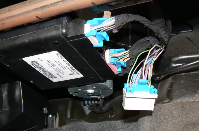
Most of the posts on edmunds.com advised doing the modifications through the space in the dash that is occupied by the radio. On my car, however, I could not get sufficient slack in the wires to do the work. I decided instead to work with the same wires at the point where they connect to the Body Control Module.
So, before you clip your yellow wire, take a few extra minutes to inspect everything you can concerning the Passlock system.
The Passlock Security System is quite simple. When the Body Control Module is programmed, it measures and stores the value of the signal on the Yellow Wire on pin 6 of the center connector, using the black wire as a reference.
From then on, each time the car is started, the Body Control Module checks to see if the signal on the yellow wire matches the stored value. If a key is not inserted into the ignition switch, and the lock cylinder is not rotated to the on position, the value of the signal will be incorrect. The Body Control Module will then send a signal to the Powertrain Control Module telling it to shut down the fuel injectors.
In some model GM cars, the signal from the ignition system is controlled by a resistor embedded in the key. In others, the resistor is embedded in the Passcode module, which is part of the ignition switch cylinder. In these systems, any key that will allow the cylinder to be turned to the on position will work, the only condition that must be met is that the cylinder must be turned to a position where a magnet engages a hall-effect switch, which connects the embedded resistor to the system, allowing the Body Control Module to read the signal value on the yellow wire and determine if it is correct.
On the 2002 Pontiac Grand Am, Olds Alero, and several other GM cars, the Ignition lock cylinder is the most likely cause of cars not starting because of security system malfunctions. Wear in the ignition cylinder causes the electronics within the security module to present a different signal to the yellow wire. When this begins to happen, the signal is no longer stable, but varies each time the key is turned in the cylinder. Changing the lock cylinder then becomes the only solution approved by the dealer.
You can avoid paying a dealer $300 - $500 to change the lock cylinder by performing a simple modification on your vehicle. But before you start, you should make sure that your vehicle is one that uses this system. Read your owner's manual, and find the section on PASSLOCK(tm). It should read in part, "After attempting to start the engine, if the SECURITY light flashes or stays on, wait ten minutes with the ignition key in ON until the light goes off." That phrase in the owners manual is the key to knowing that your system is one that can be modified in this manner. If you know that this procedure works on your car, then you can proceed with the modification.
CAUTION - If you are going to do this modification, read this entire web page thoroughly, and perform each step. Do not leave out any of the steps. I repeat.... Do not leave out any steps.
 connector with pertinent wires identified.")
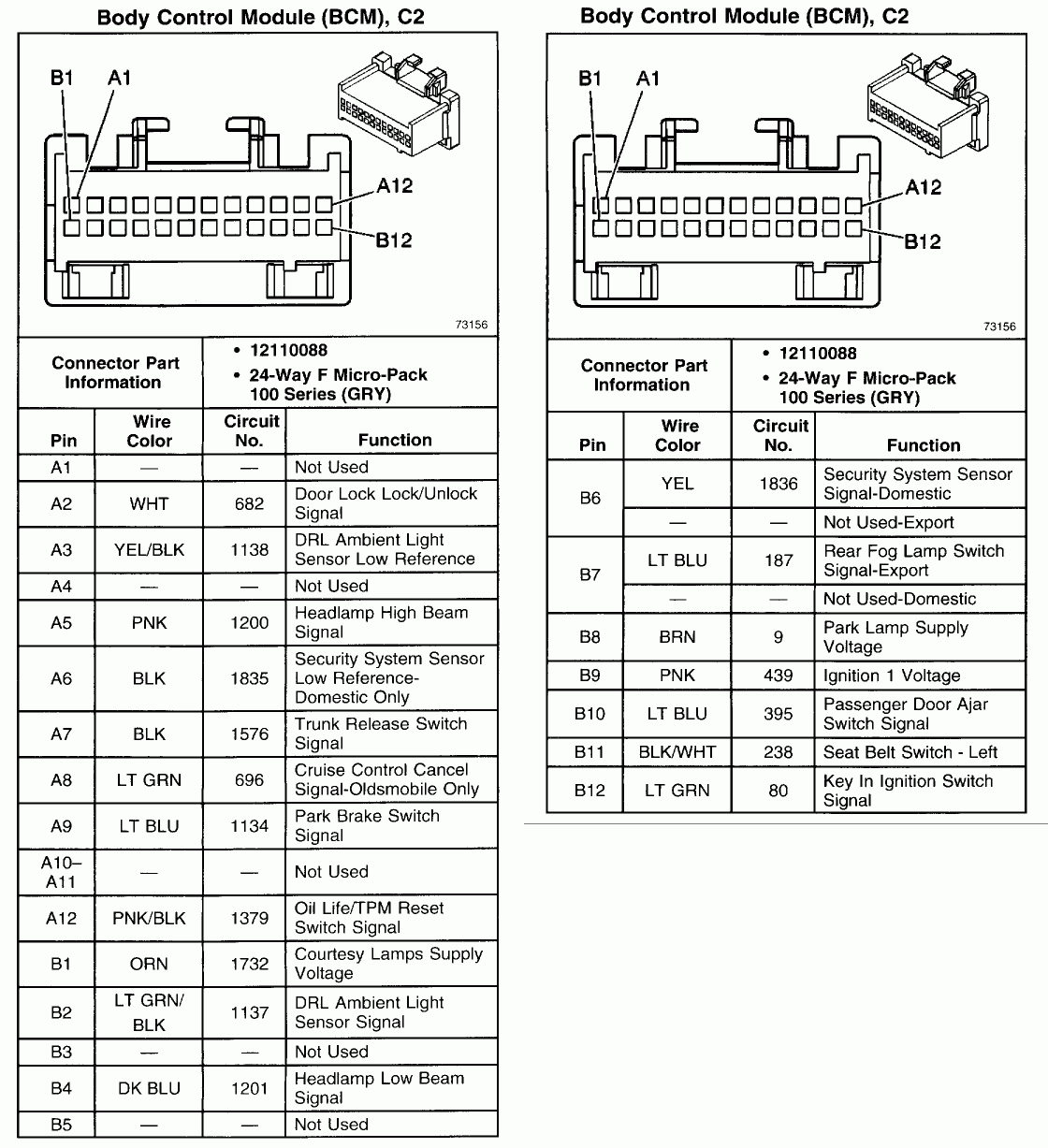
Make sure the battery is disconnected. If you have not disconnected the Grey (center) connector from the Body Control Module, disconnect it now and pull it down so that you can access the wires that go to the ignition cylinder. Pin B6 of the connector will be a yellow wire, and pin A6, which is directly opposite, will be a black wire. These are the two wires you will work with. In Figure 2 I have isolated the two wires and tied a green string around them
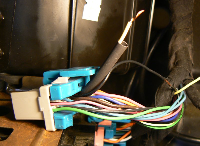
Figure 3 showing the wires we will make connection to.
Strip the insulation off of about 1/2 inch of the black wire, leaving it bare so you can solder to it. Then cut the yellow wire about 4" from the connector. Strip about 1/2 inch of insulation off the end of the wire which goes to the connector. Tape up the other wire end, bend it back and push it back into the bundle out of the way.
Now, slide a 2 1/2 inch piece of shrink tubing over the yellow wire so that you can later use it to cover the resistor you are about to solder into the circuit.
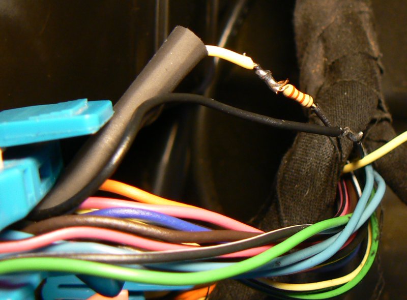
Figure 4. Resistor Soldered in place between yellow and black wire.
Take a 2200 ohm (2.2 Kohm) 1/4 watt resistor and wrap one end of it around the stripped part of the black wire several times so that you have a good mechanical contact. Then solder the joint. Make sure you use enough heat to draw solder into the joint. A 25 watt iron is sufficient. Please note... I arbitrarily chose to use a 2200 ohm resistor. Some posts have suggested reading the resistor value with an ohmmeter, but all ohmmeters don't read the same value when there are electronic components in the circuit. We will later be teaching the Body Control Module to recognize the resistor we chose, so it doesn't matter what size you use. It can be anything from 470 ohms to 11800 ohms. I suggest something between 2000 and 4000 ohms.
Wrap the stripped end of the yellow wire from the connector around the other lead of the resistor and solder it in place, making sure you have a good solder connection. If you don't know how to do electrical soldering, it may be a good idea to ask your local computer tech to give you a lesson.
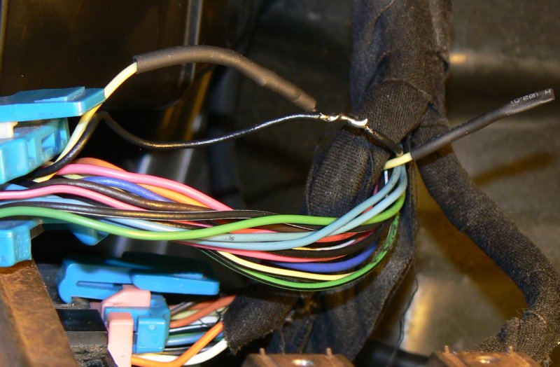
Figure 5. Shrink fit insulation applied over resistor.
Now slide the shrink tubing up so that it covers the resistor. Apply heat from a hair dryer to shrink the tubing over the resistor. The end result should look like Figure 5. Use black electrical tape to insulate the bare part of the black wire where you soldered the resistor to it.
Plug the grey connector back into the Body Control Module. Re-connect the battery Negative terminal. Try to start the car. It will probably not start, or it will start and then stop after a second or two, and the Security light will come on. This is because you have only about 1 chance in 20 that the 2200 ohm resistor is correct. That's OK, because now, we are going to re-calibrate the Body Control Module to the chosen resistor.
Turn the Ignition key to the off position if it is not already there. Then turn it to the On position. The security light should come on. Wait about 10 minutes with the key in ON until the light goes off. Then turn the ignition to OFF before attempting to start the engine again. At this time, the Body Control Module will have memorized the new value for your resistor, and the engine should start.
If the above goes well, you can replace your kick panels, and forget about the Passlock (tm) problems forever.
By the way, to get better access to the wiring on my car, I also removed the Glove box. This was quite easy, just two screws at the top edge, and one on each side hold it in place. Be sure to carefully disconnect the glove box light, and re-connect it when re-installing.
Updates - 11/17/2008If you have performed this mod, and your car does not start, and/or the security light is still on.
If everything above checks out, then you probably have a defective BCM. I hate to break the bad news to you, but you are one of the 3 percent or so who this mod didn't help. Un-do your work, and take your car to the dealer, along with a wheelbarrow full of money.
Here are a few notes that may help everyone to understand what the Passlock Security System is and how it works.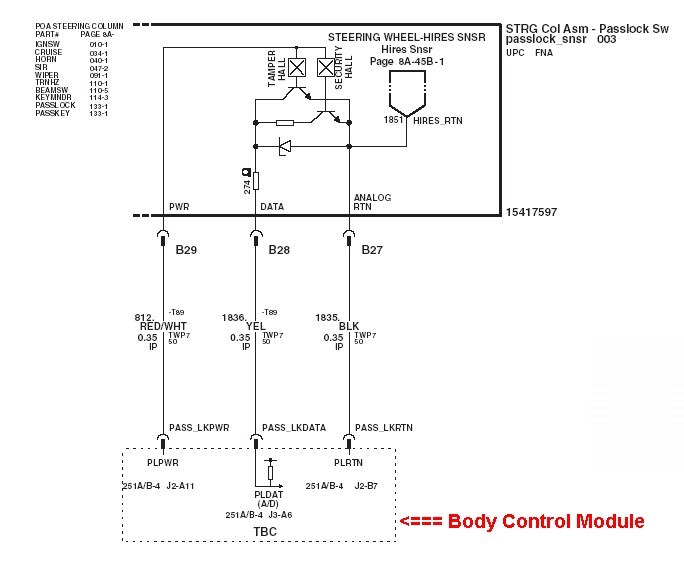
This is an excerpt from the 2003 CK Truck manual, showing the Passlock system for that vehicle. This is not exactly the same as the 2002 Pontiac Grand Am, but it is close enough for my explanation.
The three wires connecting the steering assembly at the top of the diagram to the Body Control Module at the bottom of the diagram correspond to the three wires that connect the Grand Am Ignition Module to the Body Control Module. The Red/White wire (White on the Grand AM) supplies power to the module. When the Security Hall Effect switch is closed, the transistor connected to it conducts, which effectively connects the 274 ohm plus the other resistor between the yellow and black wires. This furnishes a voltage to the Body Control Module on the yellow wire, which the Body Control Module measures, to see if it is the correct voltage. If it is, it allows the car to start. If it isn't the correct voltage, the Body Control Module sends a message to the Powertrain Control Module, telling it to shut down the fuel injectors. With no fuel, the vehicle will not run.
 The modification above simply disconnects the passlock module in the Ignition Switch from the Body Control Module, and replaces it with a 2200 ohm resistor, As you can see, the modification fixes the system only if the problem is caused by the passlock module, which is the culprit most of the time.
To the right is a diagram and pinout of the center BCM connector. On the 2002 Pontiac Grand Am, the Passlock Data wire (yellow) is on pin B6, and the ground wire (black) is on pin A6. The connector pins are the same on the Oldsmobile Alero. and Chevrolet Impala
In several posts on Edmunds.com, I have recommended to folks that they read only certain of the posts within the Pontiac Grand Am Security Passlock Problems thread. To make this a bit easier, I have copied the pertinent information here on this website. I hope this information will shed some light on problems that people are having with Grand Am's other than 2002 with manual transmissions.
Post #21-23
raycorri - Replying to: virgo58 (Jan 30, 2007 9:11 pm)
If you want the fastest way to disable the Passlock---You just need to be able to start your car one time. Start it--leave it running--put car in neutral-- remove your radio, but do not unplug it.(Let it hang)Reach inside to the left and locate 3 tiny 22 gauge wires wrapped in black friction tape.(Yellow, Black, and White Passlock Wires)These are with the Ignition switch harness. Cut the (Yellow Passlock) Data Wire (while the engine is running). Security light will come on and stay on forever--- this tells you that Passlock is disabled.(PCM is in fail enable mode)Tape up both ends of the Yellow wire. Your car will crank from now on with no worries. I would suggest that you add a toggle switch, though. Disable Passlock --- it's not necessary to add a remote starter. Do a google search for "Passlock I or II Disablement" to see the written document for adding the toggle switch.
Replying to: raycorri (Feb 01, 2007 5:10 pm)
raycorri, do you attach the toggle switch to each end of the cut yellow wire??
Replying to: bward1 (Feb 01, 2007 8:31 pm)
Yeah, that's right. You are putting the switch into the line. It will connect or disconnect the "cut wire" at the flip of a switch. You can even add a length of about 20 gauge wire so you can mount the switch in a more convenient or "hidden" location.(If you are good with wiring.)Flip the switch (while the engine is running)to turn the Passlock off. I have decided to leave mine off permanently.
Post #50
Replying to: debt (Mar 14, 2007 7:14 am)
Here you go! Also, to ginkle7--- Was your car running when you cut the yellow passlock wire? You must have the car already running! That is crucial.
Post #56
Replying to: raycorri (Mar 14, 2007 11:07 am)
Here is documentation of why this works. It is originally from these GM engineering documents for trucks. All Passlock I and II systems are the same. In most, it is actually easier to access the Yellow Data Wire near the Ignition. This is why we enter through the radio compartment. The "cut the wire" method is just an extreme shortcut to the addition of a "toggle switch". This is the old-old school method which pre-dates the "relay and resistor" bypass and the newer "bypass modules" made for remote starters. The latter two options will not work if you have intermittent wiring problems since they still utilize sending a code via the data wire. You have to be able to start your car at least once in order to trigger "fail-enable" mode. If your car will not start any longer, it's too late to cut the wire.
GM Vehicle Remote Start Capability bulletin and
Passlock Disablement for Vehicle
Remote Start Capability and
2003 and BEYOND LIGHT DUTY C/K FULL-SIZE TRUCK ELECTRICAL
In this document, look at page A29 and A30 .... and
Here is a re-write of the Truck Bulletin, modified for GM Cars
Passlock I and II Disablement - Pontiac Forums and
How to replace the Ignition Lock Cylinder by bolt 3/11/2006 w/photos.
By the way: A dealership will never disable the Passlock for you---even if they know how. I don't think a recall will ever happen either. It has to be a safety issue. That's why they programmed "fail-enable" mode for passlock. If passlock or passlock wiring was to fail while you were driving down the road, your car will not shut down. Hence, it's not a safety issue if your car will not start. Enjoy the reading material!
Post #209
For those of you who have not done it yet:
Mine is a 1997 GrandAm. I warrant what follows for 1997s only, but perhaps yours is the same.
1. The manual says to isolate the yellow data wire through the radio compartment, but I did not have to do that. Pop the top off the steering-wheel housing (it snaps on) and remove the tilt-steering lever (unscrews -- mine had some locktite on it, so be careful).
2. Now remove the bottom portion of the housing (three screws underneath).
3. BE CAREFUL! There are two yellow wires underneath -- one to the air bag, one to the ignition. Obviously, you want the one to the ignition. It is the wire "most" underneath (obvious what that means when you see it) and closest to the driver when he or she is behind the wheel.
4. START THE CAR! START THE CAR! START THE CAR! This is an essential step! If the car won't start (like mine), jiggle the wire as you turn the ignition (many of these PassLock problems are old, corroded wire connections, not the Hall sensor).
5. Clip the yellow data wire, leaving at least some wire to work with on both sections. Once the wire is cut, you may (but don't have to) turn off the car.
6. From Radio Shack, obtain SPST mini-toggle switch # 275-612 (total cost including tax: $3.17).
7. Remove switch from packaging; make sure it is in the "off" (contacts open) position (check it with a meter).
8. Strip a short section of insulation from each end of the cut data wire, slip some shrink wrap over the wires, and splice in the switch.
9. Maneuver the shrink wrap over the soldered terminals and heat to form a completely insulated splice.
10. The toggle can be left inside the housing or mounted on the underside of the lower housing section (drill a 1/4-inch hole carefully so the plastic does not melt around the drill bit).
11. Reinstall lower housing (three screws) and tilt lever (you may want to use some locktite, but I didn't). If you opted for outside mounting, screw on the locknut for the switch.
12. Snap top half of housing in place.
13. If you turned the car off, turn it on to test. It should start right up.
That's all there is to it!
Now: Don't write back and say your "theft system" light is on -- it's supposed to be on. What you have just done is disable PassLock, and YOUR CAR IS NO LONGER PROTECTED FROM BEING HOTWIRED AND STOLEN. So, you must take all the old precautions against auto theft, like locking the car and pocketing the keys.
IF YOUR BATTERY DIES (or if your local dummy repairman disconnects it to work on the car): PassLock probably will reactivate -- that's why you spliced in the switch. Flip the toggle to "on." Now, in effect, the data wire is reconnected. You must get the car started again to disable PassLock. Once started and running for more than five seconds, flip the toggle to "off." PassLock once again is disabled, and the red "theft system" light will come on. Ignore the light.
N.B.: If you accidentally (or deliberately) flip the toggle while the car is off, PassLock will reactivate, and the car must be restarted again before the toggle can be turned off again. If PassLock is engaged and the toggle is off, the car will not start. If you flip the toggle while the car is running, again PassLock will engage and stay engaged unless you flip the toggle off before turning off the ignition.
By the way, for anyone interested in a cheap way to access data on your particular vehicle, I contacted a company called "ALLDATAdiy", who have online manuals for just about every automobile. I asked them specifically if their online databank contains information about the wiring of security systems. Here is their reply:
"Hello, Thank you for your interest in ALLDATA. To answer your question, ALLDATAdiy.com does supply factory wiring diagrams and connector views for GM vehicles. All diagrams are complete and include the passlock system. With your subscription, you will have online access to all the diagrams, repair information, and detailed Factory Technical Service Bulletins/Recalls for your vehicles. Also, all the information comes from the manufacturer, and is a single vehicle slice from our Professional Product utilized by more than 70,000 shops."
Their 1 year service is quite cheap ($27.00). contact them at: http://www.alldatadiy.com
Post 560
Replying to: markjr54 (Mar 31, 2009 10:28 am)
My 2002 Impala needed a new BCM according to the ex-GM mechanic who troubleshot my Security/Passlock problem. He said he could have programmed the BCM himself, but that it would not receive the most up-to-date information so he wound up taking my car to a Chevy dealership where he once worked and his friends programmed the BCM with some special machine. He said the going rate was $95/hour for a two hour job, but they only charged him half. The guy seems like a stand-up guy and was recommended by my regular mechanic who deals primarily with Chryslers and doesn't have the GM computers that seem to be needed to do the BCM justice. This is my long-winded way of saying I think your BCM will probably need to be programmed.
As far as you not getting voltage at the fuel pump, I think there is one other thing to be considered besides the BCM. If I recall from all the threads I've read about the passlock security issue, and I've read easily over 1000 different messages, I believe the BCM sends a signal to the PCM(powertrain control module) which in turn allows voltage to pass to the fuel pump. Can anyone verify/second this sequence? IIRC, the PCM is located inside the engine compartment while the BCM is located under the dash. As others have mentioned corrosion in the BCM, PCM, fuse blades, and just about any connection in the wiring harnesses can create havoc with the Passlock system.
This is just a theory, and possibly wishful thinking on my part, but I think the newer BCMs and the newer programming for them have done away with a great deal of the security/Passlock issues on GM products. I'm thinking the engineers have allowed for greater variations in the resistance reading of the key to compensate for variances due to wear and tear in the ignition switch/cylinder. I don't believe GM has sent out any troubleshooting/maintenance bulletins on vehicles after 2005...I may be wrong on that. In fact I'm trying to recall if GM has ever had a Passlock issue with any of their Buick models.