|
This article describes how to bypass the "Passlock Sensor" on several models of GM cars. No soldering is required. You must perform all the steps.
The Problem
You try to start your GM car. The engine starts, but dies in one or two seconds, and the "SECURITY" light begins flashing.
OR ... You are driving along, and for no apparent reason, the "SECURITY" light comes on solid and stays on. After you shut down your vehicle, the next time you start your car the SECURITY light is on solid.
This is a common problem on the following GM Cars
1999 - 2004 Oldsmobile Alero
1997 - 2003 Chevrolet Malibu
1999 - 2004 Pontiac Grand Am
The problem is usually caused by the "Passlock Sensor", which is part of the Ignition Lock Module. Your owner's manual gives you the following advise
"After attempting to start the engine, if the "SECURITY" light flashes or stays on, wait ten minutes with the key in ON until the light goes off. Then turn the ignition to OFF before attempting to start the engine again."
This normally works! Unfortunately, a few weeks later, you will probably have to go through the entire routine again. It will get under your skin really bad the third time, and after that, you will start kicking the dash and swearing. This web page will guide you through the steps necessary to bypass the "Passlock Sensor" on a 2002 Pontiac Grand Am, and keep the "SECURITY" light off forever. The steps necessary are similar on the other models listed above. There are generally only minor differences in how to get the radio out to get to the wires.
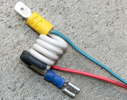
In GM cars, there is a bundle of three wires which go from the Body Control Module to the Ignition Switch. They are Black (analog return), White (power), and Yellow (analog data). The Yellow wire is circuit #1836, and this is the wire that furnishes an analog signal to the Body Control Module to tell it that a key has been used to turn the lock cylinder to the ON position.
The three wires can be accessed by removing the radio from the dashboard, and reaching through a hole in the radio compartment toward the steering wheel. This article describes how to:
- Build a cheap, simple circuit to take the place of the Passlock Sensor
- Find the three wires that connect the Passlock Sensor to the Body Control Module and substitute our circuit for the Passlock Sensor.
- Perform the "Relearn" Procedure so that our Body Control Module recognizes our new circuit.
|
Bypassing the Passlock Sensor - Step by Step
|
Note: Many of the images on this page can be enlarged by right clicking on the image, and selecting "View Image"
Supplies Needed
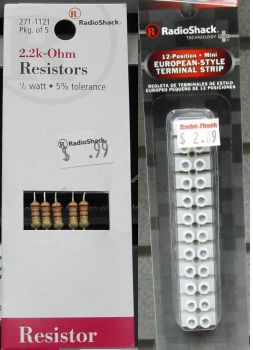 Go to Radio Shack and buy a Mini Terminal Block, and a package of 2200 ohm (2.2k-Ohm) resistors. You won't need all of them. but you probably can't buy just one. Go to Radio Shack and buy a Mini Terminal Block, and a package of 2200 ohm (2.2k-Ohm) resistors. You won't need all of them. but you probably can't buy just one.
If your local Radio Shack store has gone out of business, you can order the parts from Digi-Key Electronics. Here are links to the 2.2k-ohm Resistor and the Terminal Block
You will also need some tools:
- Needle Nose Plires
- Small Screwdriver
- Wrenches and Nut-Drivers
- Sharp knife for cutting and stripping wires
- Large Screwdriver
Building A Dummy Passlock Sensor
NOTE: IF YOU WANT TO AVOID BUILDING THE DUMMY PASSLOCK SENSOR, YOU CAN BUY ONE ON E-BAY. HERE IS THE LINK GM Passkey NO start Bypass
Cut two terminals off the end of the terminal strip. Set the rest of the terminal strip aside.
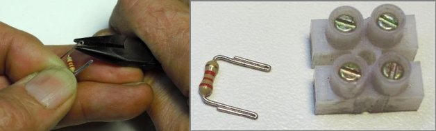
Takle one of the 2200 ohm resistors and bend the leads as I'm doing here. Then cut off the excess lead wire. (The color code for the resistor is three red bands.) When you've finished the above steps, you will have the two parts shown on the right side of the above photo.
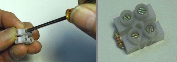
Insert the resistor leads into one side of the terminal block and tighten the terminal screws down on both the leads. Now you have created the module in the right side of the above photo. You will use this module to bypass your security system without having to solder anything.
|
Replacing the Passlock Sensor with Our Module
Important: Disconnect one of the terminals from the battery before doing any of the following.
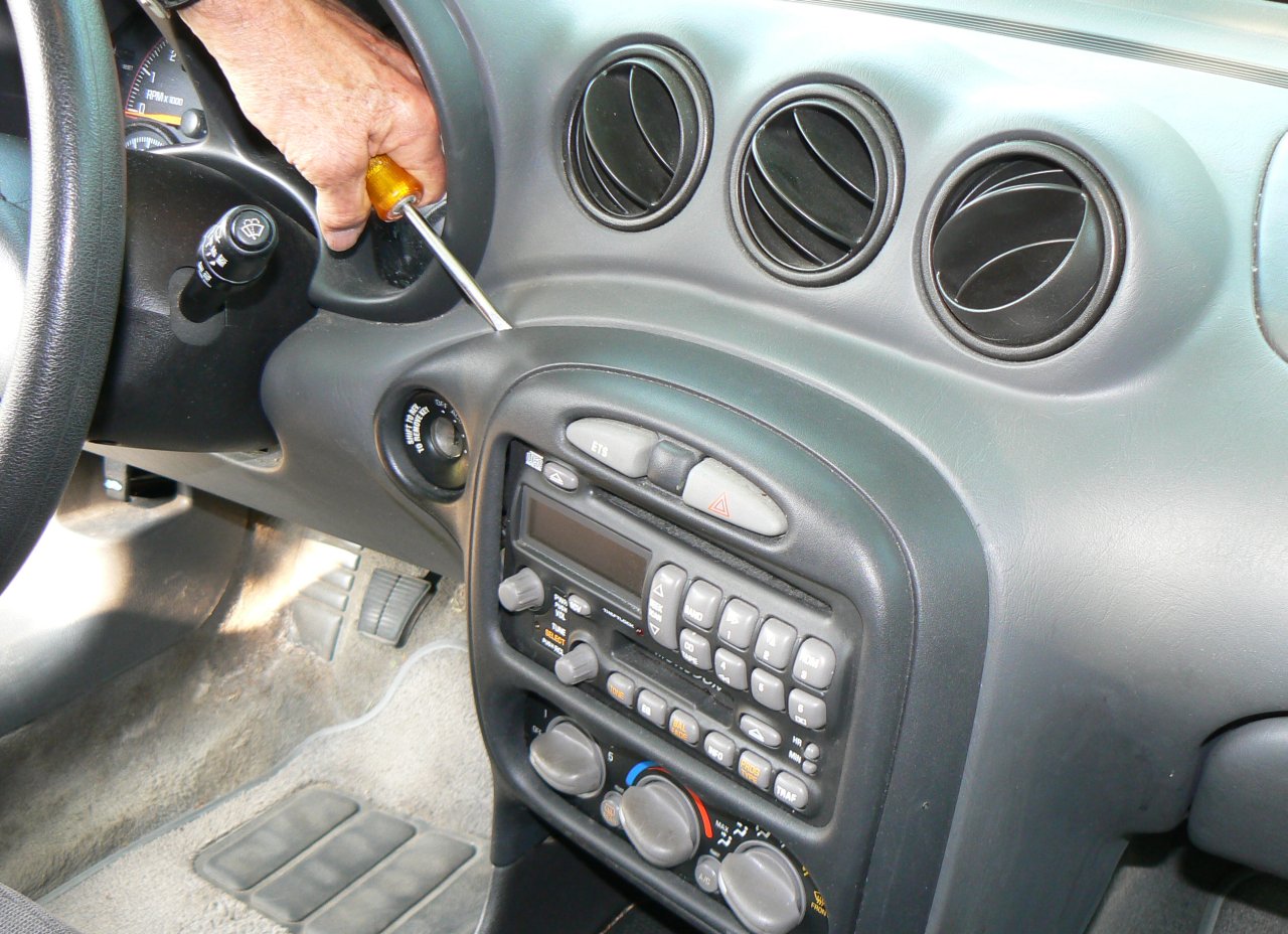
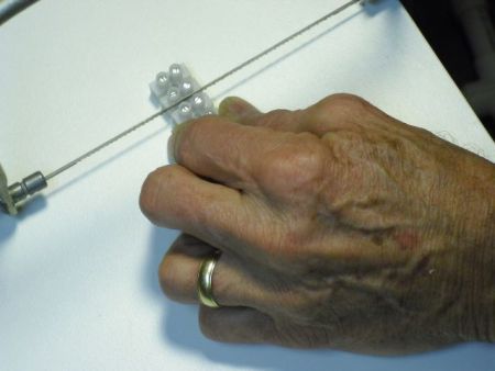
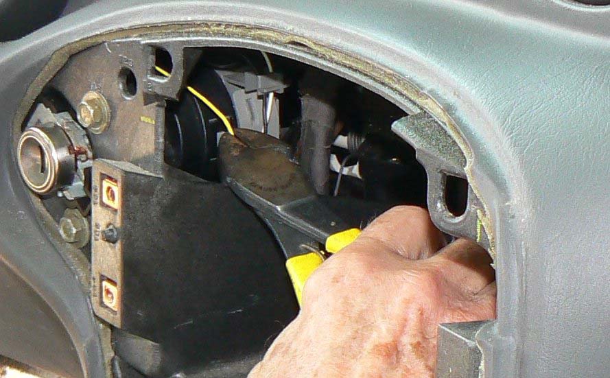
Remove the bezel around your radio. You can pry it loose with a large screwdriver, or a sturdy dinner knife. Once you get it loose, disconnect the cables that go to the two lights at the top of the bezel, and the cigarette lighter socket. Then you can set the bezel aside
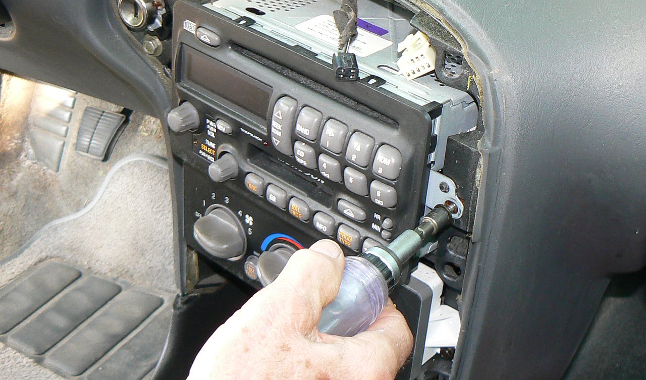
Use a 5/16 inch socket to remove the three screws holding the radio in place. Pull the radio out of it's cavity. Disconnect the wiring connector and the antenna wire, and set the radio aside.
|
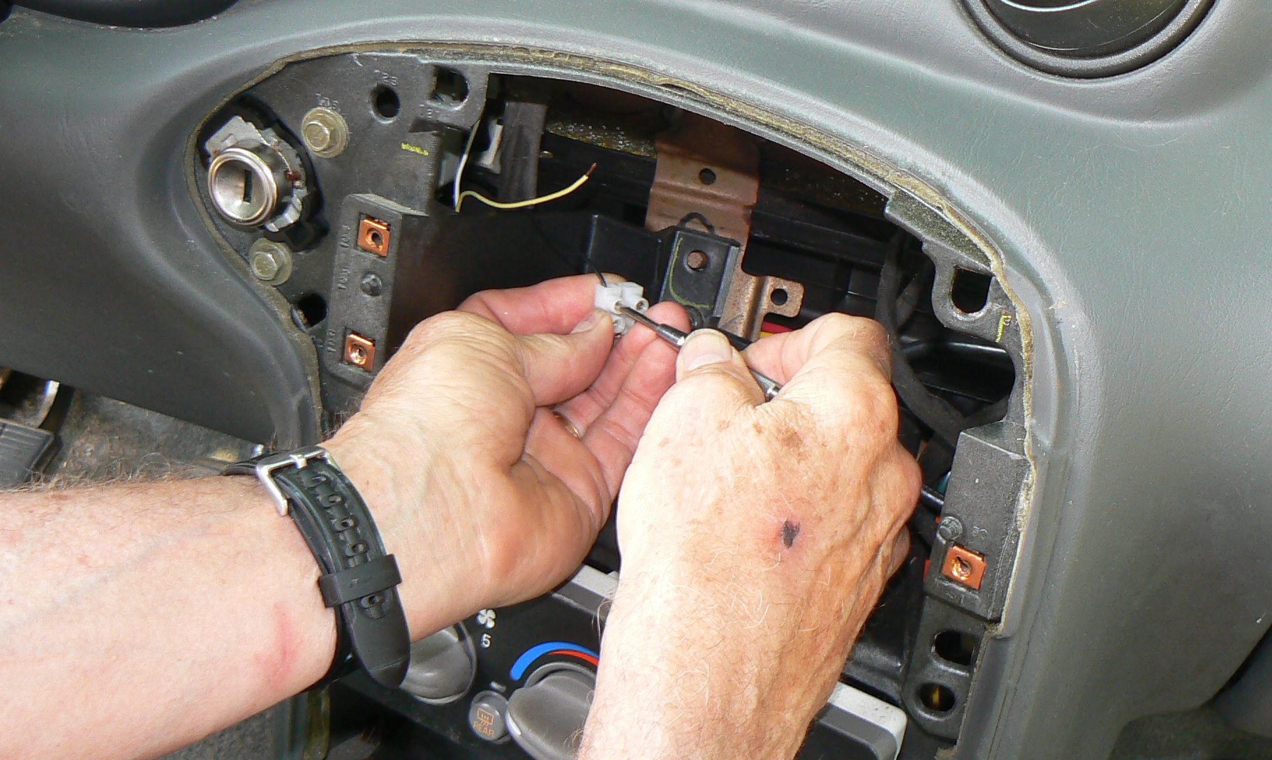
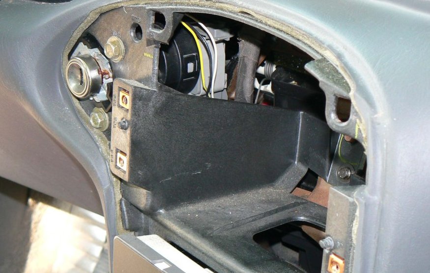
On the left side of the radio cavity, there will be an opening, through which you will be able to see the Ignition Switch. Three thin wires, possibly taped together with fabric tape, will be visible coming from the top of the ignition switch. They will be near the end of the switch where the key is inserted. If they are wrapped with black fabric tape, unwrap them and separate the three wires so you can determine which is yellow, black, and white.
CAUTION: If a remote start or alarm system has been installed on your vehicle, the wiring has probably been modified. In that case, do not continue with this project. It will not work!
|
|
|
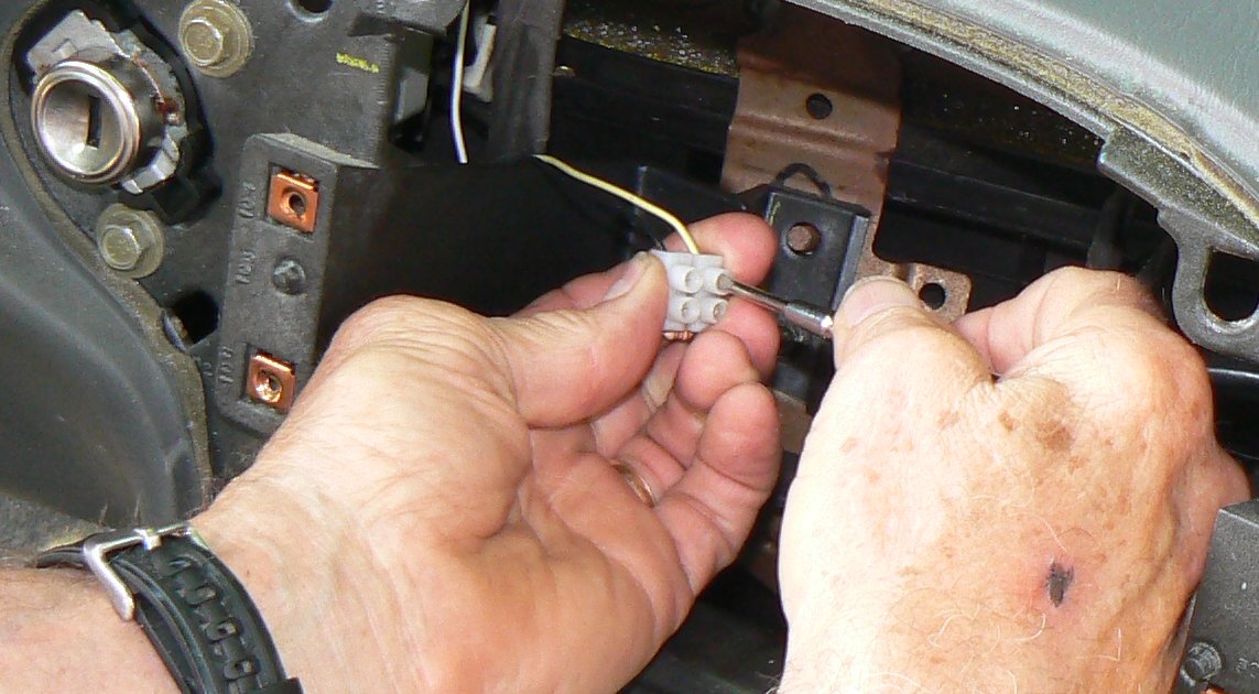
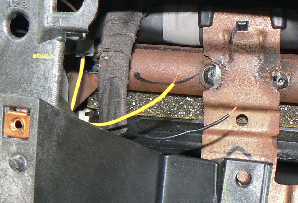
Cut the yellow wire, and the black wire, leaving as much wire as possible on the ends that do not go to the ignition switch. Insulate the ends of the two wires that go to the ignition switch, and push them back out of the way. You are finished with them.
Strip 3/8 inch of insulation from the end of the black wire and then twist the bare strands together Do the same with the yellow wire.
Push the stripped end of the black wire into one of the empty holes of the terminal block of your Dummy Passlock Sensor. (see photo above) Tighten the screw to secure it in place.
Push the stripped end of the yellow wire into the other terminal of your Dummy Passlock Sensor (see photo) and tighten the screw to secure it in place. Your re-wiring is now done. Connect the battery cable back to the battery. You are ready to perform the relearn procedure.
The 10 Minute Re-learn Procedure
Insert the Key into the ignition switch and try to start the car. It should start, and then stall, with the "SECURITY" light flashing. (In rare cases, the car may keep running and the security light will not illuminate, but that only happens if you are very lucky.) If the Security light flashes, leave the ignition in the ON position and wait up to 15 minutes. The Body Control Moudle should re-learn the security signal, and the "SECURITY" light should go out. When it does, Turn the ignition OFF for five (5) seconds, and then try to re-start the car. The "SECURITY" light should remain off this time, and the car should keep running. If not, don't give up. You may have to try the longer re-learn procedure described below. If successful, re-install your radio and bezel, gather up your tools, pat yourself on the back, stuff an envelope full of as much cash as you think my advise was worth, and send it to:
Security Fix
1131 Outer Drive
Fenton, MI 48430
The 30 Minute Re-learn Procedure
If the above 10 minute re-learn procedure did not turn off your "SECURITY" light and enable you to start your vehicle, There are three other components which may be causing your problems.
- Broken wiring or corroded connectors
- The Body Control Module (BCM)
- The Powertrain Control Module (PCM)
Before replacing the BCM or PCM, you should first try the 30 minute Re-learn Procedure which is described in the GM Shop Manual. Here it is in it's entirity.
30 Minute Learn Procedure
Tools Required: None
- Turn ON the ignition, with the engine OFF.
- Attempt to start the engine, then release the key to ON (vehicle will not start).
- Observe the SECURITY telltale, after approximately 10 minutes the telltale will turn OFF.
- Turn OFF the ignition, and wait 5 seconds .
- Repeat steps 1 through 4, 2 more times for a total of 3 cycles/30 minutes. The vehicle is now ready to relearn the Passlock Sensor Data Code and/or passwords on the next ignition switch transition from OFF to CRANK. IMPORTANT: The vehicle learns the Passlock Sensor Data Code and/or password on the next ignition switch transition from OFF to CRANK. You must turn the ignition OFF before attempting to start the vehicle.
- Start the engine. The vehicle has now learned the Passlock Sensor Data Code and/or password.
- With a scan tool, clear any DTCs if needed. History DTCs will self clear after 100 ignition cycles.
Finally, If nothing you have done so far has enabled you to start your car and extinguish the "SECURITY" light, check to make sure your wiring is good between the bypass module you created and your BCM.
The BCM is located under the glove box behind a kick panel that can be easily removed for access. Two fasteners hold it in place. One is a hex-head screw located about 2 1/2 inches below and to the left of the lower left corner of the glove box door. The other is a "Push Fastener" located just below the right lower corner of the glove box door. To remove this fastner, first pull out on the center plug of the fastener, and then pry the fastener out of the hole. Take out the kick panel and you will find something that looks like this: (the center connector will be plugged in)
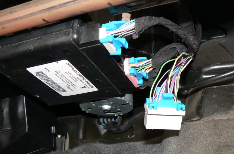
- Disconnect all three connectors from the Body Control Module.
- Remove the Body Control Module by sliding it to your right. It takes a little effort, but it will come loose. Inspect the connectors carefully to make sure they are not corroded. Shake the unit and listen for water inside.
- If there is no problem with the Body Control Module, slide it back in place, making sure it is secure in it's mount.
- Inspect the three connectors on the wiring harness to make sure all contacts are clean and not corroded.
- If the car was starting correctly before you began disassembly, it is 90% safe to assume that the Body Control Module is functioning correctly. (Nothing is a sure thing!). Re-connect the two outside connectors to the Body Control Module. Leave the center connector hanging down.
- With an Ohmmeter, measure the resistance between pins A6 and B6 of the center connector. (not the plug on the BCM, but the connector on the end of the wiring harness.) The resistance should be approximately the same as the resistor you connected into the circuit. (about 2200 ohms. [2.2Kohms]) If not, you have a wiring problem and you will need a wiring diagram for your vehicle to make repairs. You will find the 2002 Pontiac Security System Wiring diagram at the bottom of this article. Right click on it and choose "View Image" to get a full size view of the wiring diagram.
The above constitutes almost everything I know about the Passlock II Security system on GM vehicles. If you can't fix your "SECURITY" light problem with this information, I'm afraid you're going to have to bring it to a GM dealer and spend a wheelbarrow full of money to have them look at it. It may help to print out a copy of this website and bring it along so the GM mechanic can familiarize himself with the Passlock II system. Most of them haven't the foggiest idea how the system works. If you find one who does, E-mail me with the dealer's name, and the name of the mechanic. We should give him credit for knowing more than any other GM mechanic on earth.
The passlock circuits for the 2002 Grand Am
The modification to the passlock circuit for the 2002 Grand Am. The resistor takes the place of the circuitry in the passlock module
Copyright © 2002 - 2026 Bergerweb.net.
Page modified: October 10 2021.