|
|
|
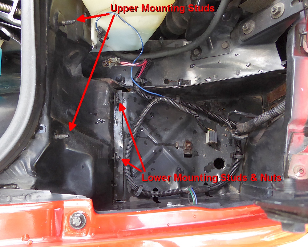
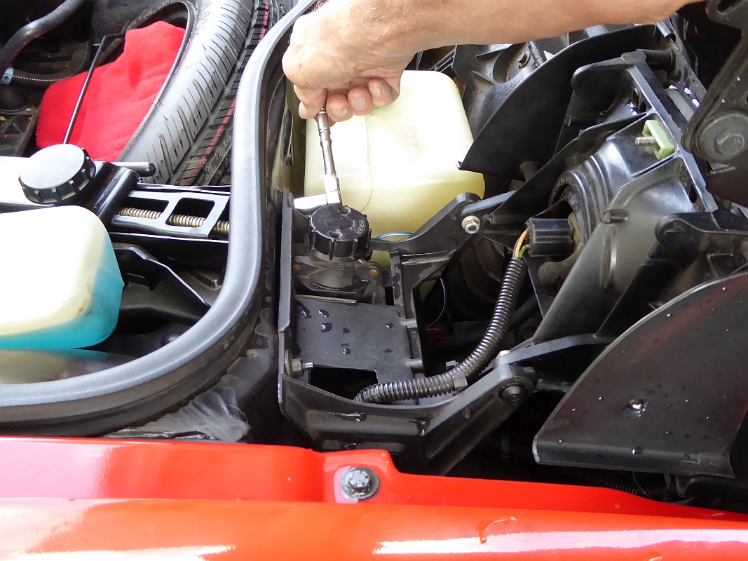
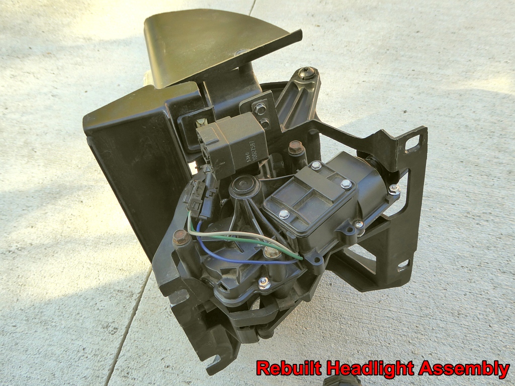
Mark the position of the headlight assembly with a scratch-awl so that you can re-install it in exactly the same position. With a 1/4" drive ratchet and a 10 MM deep socket, reach through the opening behind the headlamp and loosen the two botton nuts on the headlight assembly. You may need to use an inspection mirror to find them. The photo above on the left with the headlight assembly removed shows where they are located.
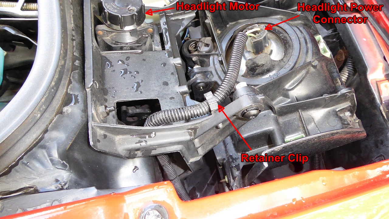
Remove the two top nuts holding the assembly in place. Now disconnect the body wiring from the headlight assembly. The connector that goes from the body wiring to the bottom of the headlight relay is not easy to unplug, but you will be able to manage that after lifting the assembly up slightly. If you find that too hard, you can remove the two screws that hold the relay in place and then turn the relay over for better access to the connector.
Once the headlight assembly is disconnected, you can remove it from the vehicle. You will have to manually open the headlight door to give yourself clearance to get the assembly out.
|
Remove the Motor from the Headlight Assembly
|
|
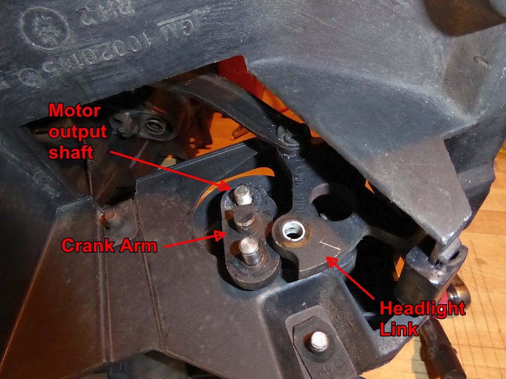
The crank arm attached to the output shaft of the motor is held to the headlight link by a "C" clip. pry the clip out of it's slot, using a small screwdriver blade. Be careful not to let it snap out of the slot and fly across the room, never to be seen again.
Lift the headlight link free of the crank arm stud. Note the position of the arm so that you can later re-install it in the same position.
|
|
|
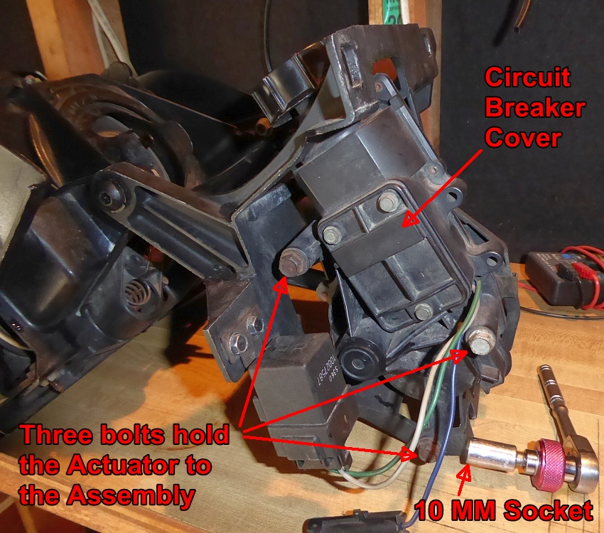
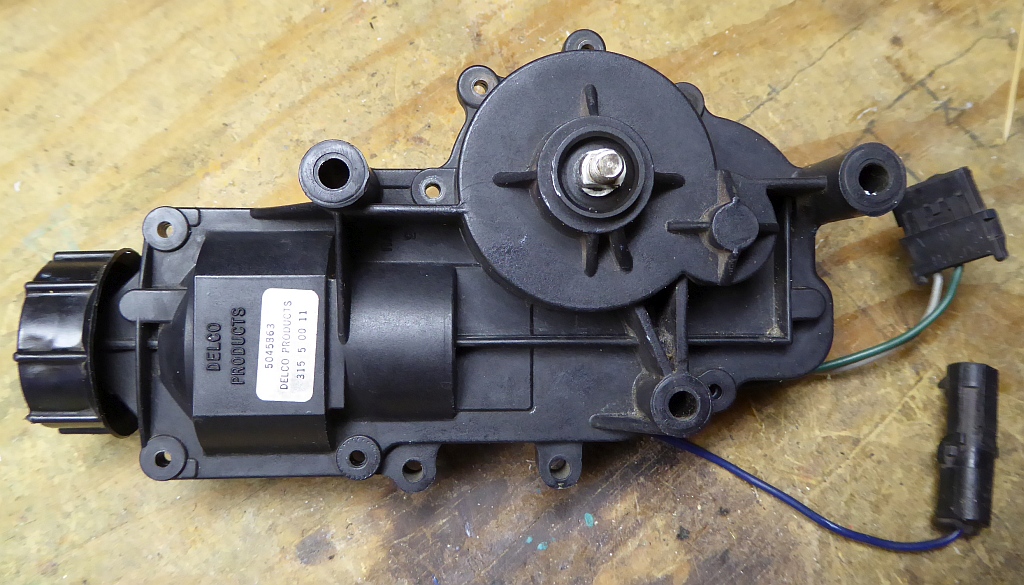
Remove the three long bolts that hold the actuator to the assembly (10 MM socket) and remove the actuator from the assembly. You are now ready to disassemble and rebuild the actuator assembly.
|
|
Disassemble and Rebuild the Actuator Assembly |
|
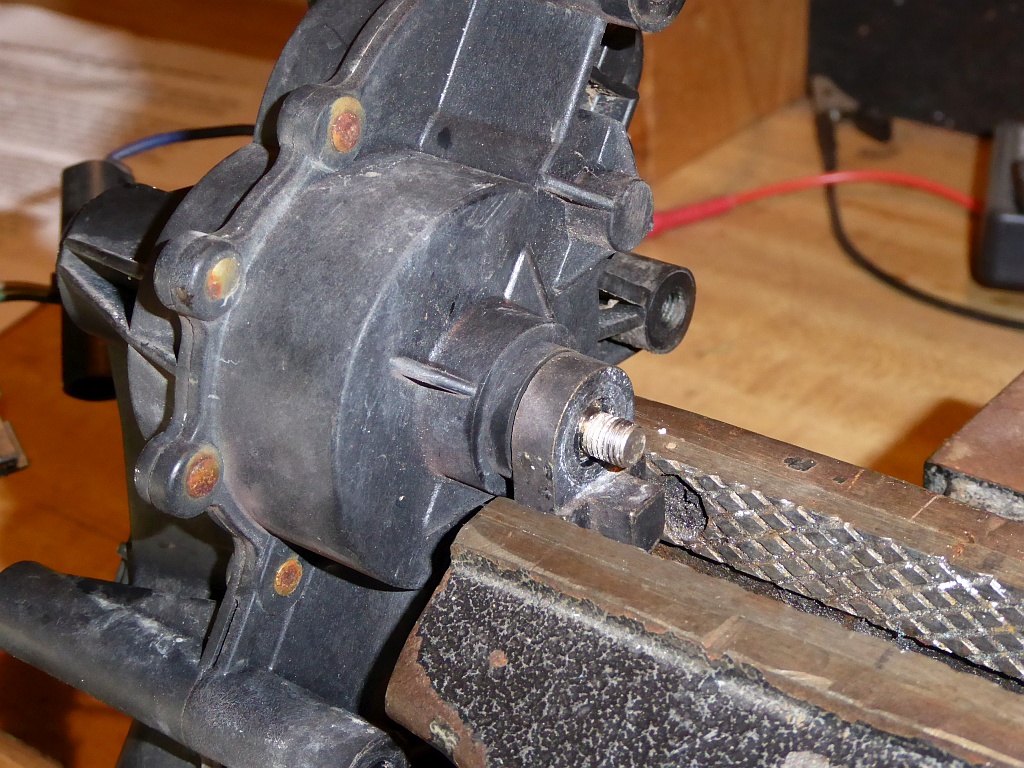
You will need to remove the crank arm from the actuator output shaft. To do so, remove the nut from the shaft (11 MM socket). Clamp the crank arm in a vise and use a rubber mallet to strike the end of the shaft to drive it out of the crank arm. You may use an ordinary hammer, but if you do, place a piece of wood against the end of the shaft to avoid damaging the threads with the hammer. Do not strike the shaft directly with a steel hammer.
Remove the three screws (1/4" socket) that secure the Circuit Breaker cover, and remove the cover.
|
|
|
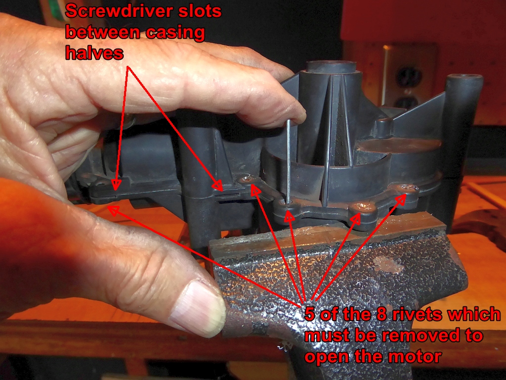
Secure the motor in a vise, being careful not to damage the case. Use a 1/8" drill bit to cut away the flanged end of the eight rivets that hold the motor housings together.Be careful to drill only far enough to remove the flanges, and not enlarge the holes in the housing. You will need a small diameter rod to punch the rivets out of the holes, once the flange is cut away. Another method is to use a Dremel Moto-Tool with a small grinder bit to grind away the flange of the rivets. During re-assembly, you will replace the rivets with screws and nuts
|
|
|
Locate the slots between the two halves of the casing. Use a flat screwdriver to separate the two halves. Once they are free of each other, raise the end of the casing opposite from the motor knob so that half clears the knob and can be removed. Before doing anything else, take a photo of the position of the magnets that surround the motor armateur so you will know which way they should be re-assembled. If necessary, make markings on the magnet housing indicating their orientation. If you re-assemble the magnets in the wrong direction, the motor will run backwards..... not good
|
|
|
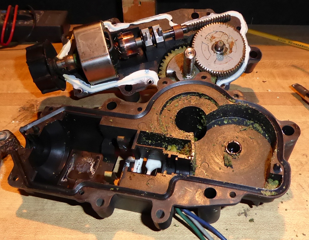
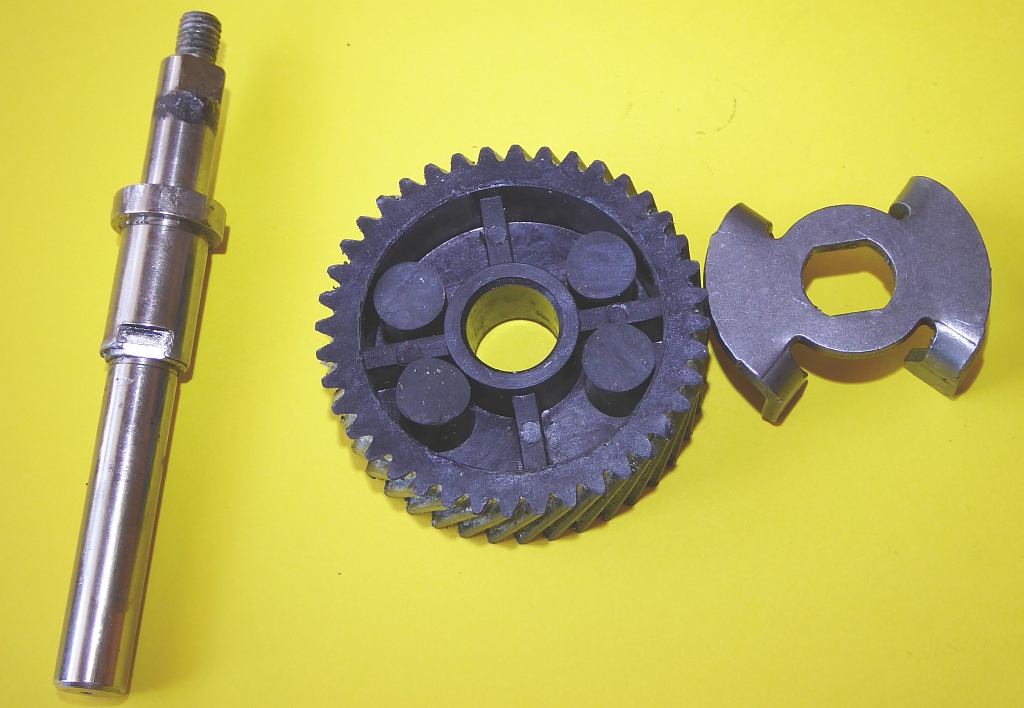
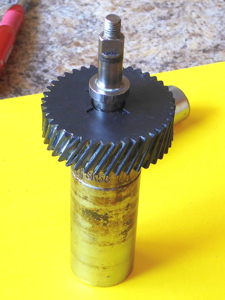
Remove the gears and shaft assembly from the casing and clean both halves of the casing and the gears thoroughly with alcohol, compressed air, and cleaning brush. Don't forget to clean the worm gear as well.
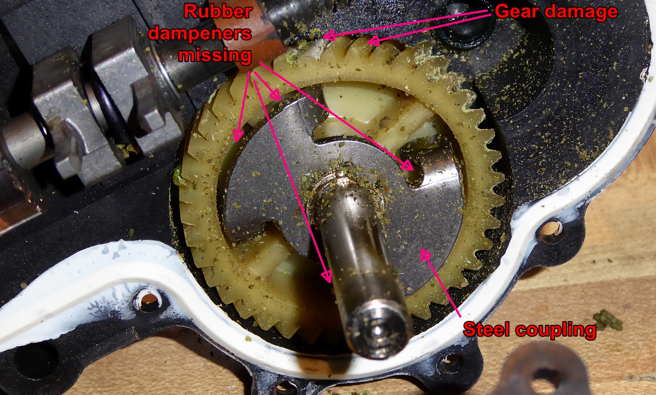
Examine the gears, especially the nylon one. You may find that the rubber bumpers are worn or missing, and that some teeth are missing from the gear. Your kit contains a new gear and new rubber bumpers.
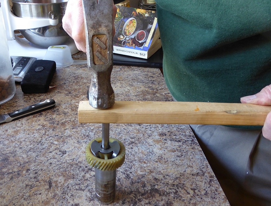
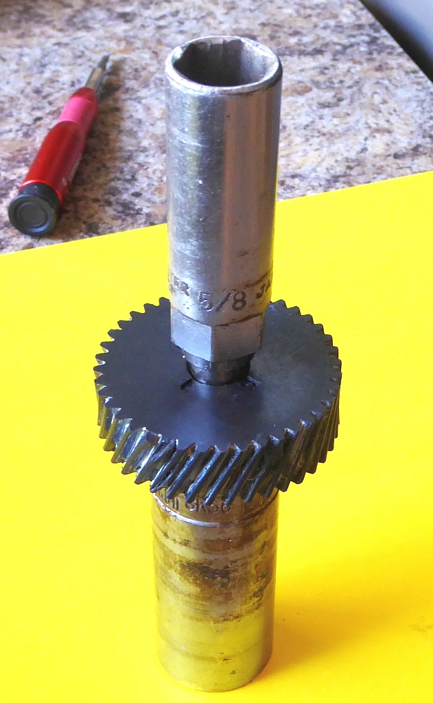
Press the nylon gear and steel coupling off the non-threaded end of the shaft. To do this, I placed the threaded end of the shaft into an 18MM deep socket and rested the gear on the rim of the socket. (see photo above right) Do not hammer directly on the end of the shaft to drive it out of the coupling. Protect the end of the shaft with a piece of hardwood. Next clean the shaft and coupling thoroughly.
|
|
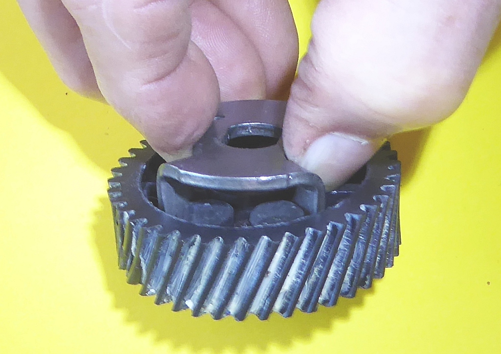
Set pairs of rubber bumpers on either side of two ribs in the new gear on opposite sides of the shaft. Then press the coupling over the rubber bumpers, capturing them between the coupling and the new gear.
|
|
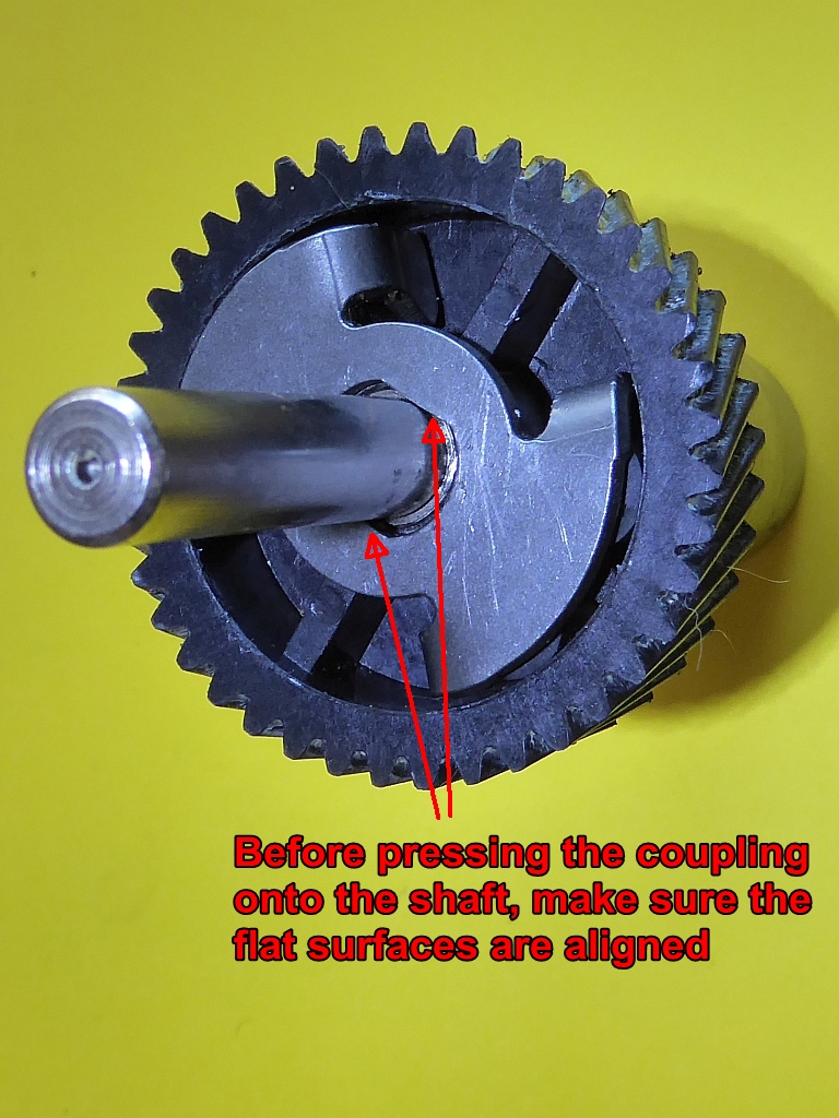
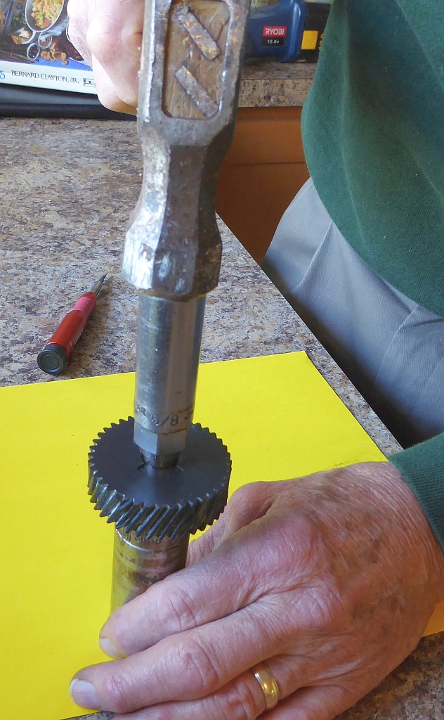
Re-install the new gear and coupling assembly onto the shaft. Align the flat spots on the shaft with the flats in the coupling, and press back to the original position. To press the coupling back into place, I used two deep sockets... a 18 MM, 1/2 inch drive on the coupler side, and a 5/8 inch, 3/8" drive on the gear side. (see photo). The drive end of the socket, when slipped over the shaft, will rest against the flange on the shaft, allowing you to hammer the shaft into place without damaging it.
|
Rebuilding the Actuator
|
|
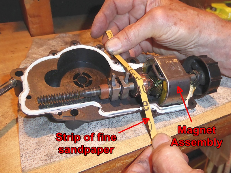
If the commutator of the motor is not shiny, It may not make good contact with the brushes, causing weak torque, or even intermittent operation. Clean the commutator with a strip of #1000 sandpaper. You may remove the unit from the housing to make this easier, but if you do, make sure you mark which side of the magnet assembly goes into the large half of the casing, and which side goes into the other half. If you get them backwards, the motor will run the wrong way. After cleaning, examine the commutator for any possible shorts between elements and remove with a sharp blade. Examine the brushes, and if they are heavily worn, replace them.
|
|
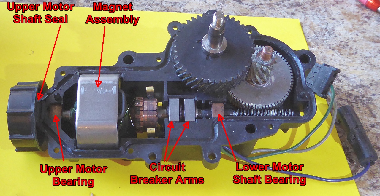
Re-assemble all the parts of the actuator into the larger half of the case (that does not have the hole for the output shaft). (see photo) Make sure you get the following parts into their respective slots. Upper motor shaft seal, Upper motor shaft brass bearing, Magnet assembly, Circuit breaker arms, Lower motor shaft bearing.
Lubricate all bearings and rotating parts with an application of white lithium grease. Be careful not to allow any grease to get on the brushes or commutator.
|
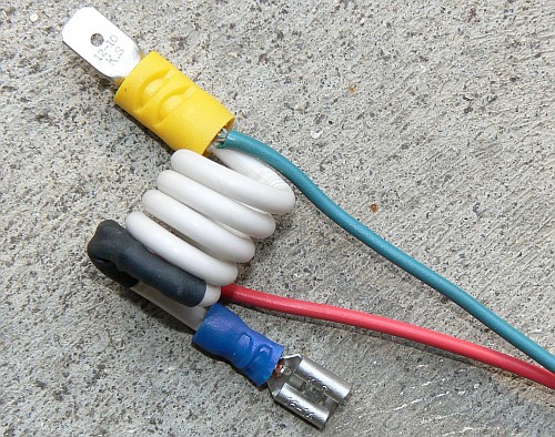
Re-join the two halves of the case, making sure all the bearings and seals are properly aligned. This is critical to the motor operation. With the two halves held together by a couple of screws to replace the removed rivits, insure that the motor is not binding. At this point, if you have a 6 volt battery or power supply, you can test the motor operation by applying power to the green and blue wires. The motor should rotate, and reversing the polarity of the power should reverse the direction of rotation.
Replace the remainder of the rivets with the screws and nuts provided in the kit. Replace the brush access cover. Don't forget to replace the O-ring around the output shaft before replacing the crank arm onto the output shaft. As you tighten the retainer nut onto the shaft, the crank arm will be pressed into place.
|
Reinstall the actuator into the headlight assembly, using the original three long bolts. Re-connect the link arm to the crank arm and install the c-clip. Check the lubrication of the link assembly
Lower the assembly into the vehicle and re-connect the wiring to the proper vehicle connectors. Make sure you get the lower slots of the assembly over the lower mounting studs and behind the nuts. Install the mounting nuts on the top mounting studs. Make sure to position the assembly according to the marks you made when you removed it. With the headlght in the up position, reach through the opening and tighten the lower mounting nuts with a 10 MM deep socket.
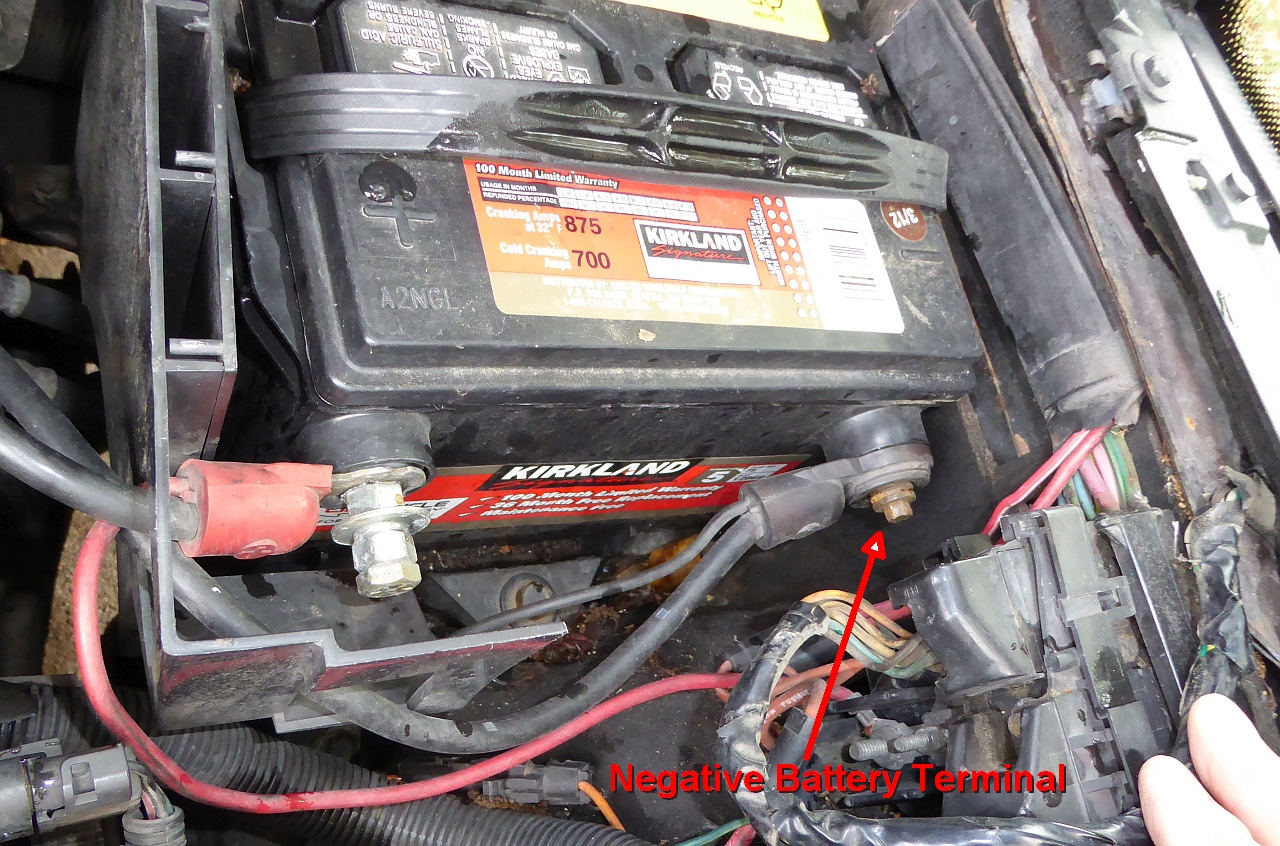
Manually lower the headlight. as you get near the end of travel, slowly turn the motor knob counterclockwise until you hear the limit circuit breaker click. Re-connect the battery. Turn the ignition switch on and test the operation.
|