 |
| Home |
| Assembly Notes |
| More Speed |
| More Power |
| An Accurate Speedometer |
| Relocate Controller |
| 72 Volt Mod. |
| Technical Notes |
| My Repair Record |
| Environmental Issues |
| Michigan Moped Law |
|
|
The following are some notes on testing and evaluating electric mopeds. After riding my XB-500 for several weeks, I became interested in finding out just how well the bike performed compared to other electric bikes. Most notably, I wanted to measure how much power was being drawn from the battery under heavier than normal loads, such as hill climbing. After doing modifications on my controller, I wanted to find out how much difference these modifications made, and whether they were reasonable as far as not damaging the bike. Here are some notes on my testing and measurement methods.
- How to measure the slope (or grade) of a hill
- Electrical Resistance of Copper and Steel Wire
- Building a Shunt to Measure High Current Drain
1. How to Measure the Slope of a Hill
Most of my knowledge about the X-Treme bikes comes from a very good forum called visforvoltage.org. The contributors to this forum have done a lot of work on documenting the modifications they have made on their own bikes, and publishing that information for the benefit of other electric bike owners. I credit them with inspiring me to add more information to the pile that is already out there, and to put forth some ideas and suggestions that will help others become a little more scientific in their testing.
Three terms are used interchangeably to define how steep a road is... slope, grade, and pitch. They are all measured the same way. The pitch of a hill is the vertical rise divided by the horizontal distance, and is stated in percent. A road that rises 5 feet vertically for every 50 feet of travel horizontally has a pitch of 10%. (5 / 50 = 0.10)
As I read through some of the threads, I found myself wondering what people meant when they said things like "After the modification,my bike will now climb a pretty steep hill on the way to work". In the hope that we can eventually define "a pretty steep hill" I would like to explain my method of measuring the slope, or pitch, of a road. My method does not require any sophisticated equipment. The most expensive thing I use is a 4 megapixel digital camera mounted to a tripod. As a bonus, my tripod has a bubble level attached to it, but this is not entirely necessary.
The method involves taking a photograph of the hill from one side of the road looking across the road, as shown in the following photograph. The photograph must have something in it that is a vertical reference... something known to be perfectly vertical.
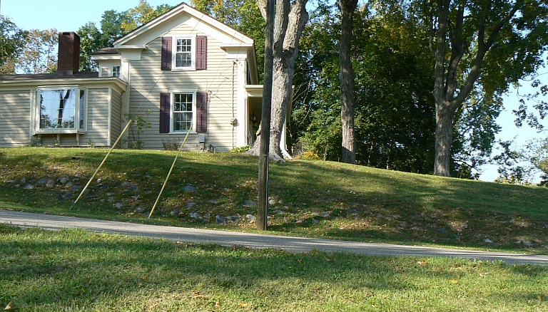
Before I took this picture, I was careful to make sure that my camera was level. As you can see, I did a pretty good job, because the front edge of the house is perfectly perpendicular. When I chose the location for this picture, I originally had in mind, using the telephone pole as my vertical reference.
 It wasn't until I viewed the photo on
my computer screen that I realized that the telephone pole is not
perpendicular, but it's very likely that the edge of the house is.
I was very lucky that my photo was perfectly level , so I would
only have to make one measurement to calculate the slope of the
road.
It wasn't until I viewed the photo on
my computer screen that I realized that the telephone pole is not
perpendicular, but it's very likely that the edge of the house is.
I was very lucky that my photo was perfectly level , so I would
only have to make one measurement to calculate the slope of the
road.
You should also note that the far edge of the road is well defined, so I can use that as a horizontal reference to do my measurements. If there were a visible center strip on the road, that would be even better, since these are usually very straight.
Once I had downloaded the photo to my computer, I used a free photo viewing and editing program, IrfanView, to aid in making measurements. IrfanView allows you to use the cursor to select a rectangular area of the photograph. It then tells you across the top of the program window how wide and tall the selected area is. I selected a rectangle whose upper left corner was on the far edge of the road, and whose lower right corner was also on the far edge of the road. (see the blow-up below)
In this case, the road rises 30 pixels for every 362 pixels horazontally. It doesn't matter that we are measuring in pixels rather than feet, the percentage will be the same. Dividing 30 by 362, we get .0829, or a pitch of 8.29%
The measurement would be only slightly more complicated if the edge of the house had not been so perfectly lined up with the vertical axis of the photograph, I would simply have had to measure the slope of the edge of the house in pixels, calculate the pitch of the entire photo, and add (or subtract) that to the calculated road pitch.
I hope in the future, many others will be able to use this simple technique to determine road steepness. By the way, to get more accurate measurements, you may want to place in the photograph, a perfect vertical reference. A carpenter's plumb line (a string with a weight on the end of it) could be hung from something in the photograph to indicate perfect vertical.
2. Electrical Resistance of Copper and Steel Wire
The "Shunt Mod" for the XB-500 and XB-600 bikes is very popular, and is discussed in many threads on visforvoltage.org. The following tables could be helpful for those who would like to take a scientific approach to modifying their bikes. These tables list the resistance of steel and copper wire of various sizes.
|
|
||||||||||||||||||||||||||||||||||||||||||||||||||||||||||||||||||||||||||||||||||||
For example. I wanted to do a shunt mod on an XB-500 controller. Normally, the current limit on the XB-500 bike is 15 amps. This limits the bike's power to about 700 watts. For climbing short hills, I would like to make the controller allow 25 amps, which is a 60% increase in power. After some measurements, I found that the limiter circuit begins limiting the current when the voltage across the shunt wire is 50 millivolts.
By calculation, ( R = E / I ) that means that the shunt wire
resistance is 0.0033 ohms. I need to change the total shunt
resistance to 0.002 ohms. To do this, I need to calculate the size
of a resistor to place in parallel with the existing shunt wire.
The formula for resistors in parallel is:
1/R1 + 1/R2 = 1/Rt
I want to calculate a value for R2, so... 1/R2 = 1/Rt - 1/R1,
or
1/R2 = 1/.002 - 1/.0033 and solving the right side gives us
1/R2 = 500 - 303.03 or 196.97 thus... R2 = .00508 ohms
Let's assume I decide to use 18 gage solid copper wire for my added shunt. Referring to the table, 18 gage copper wire has a resistance of 6.385 ohms/1000 feet, or 0.000532 ohms/inch. So I will need about 10 inches of wire for my shunt. I don't know if I can get that much wire in the space available without shorting it to something, so I need something with more resistance. I decided to use 16 gage fence wire, which is available at Lowes and Home Depot stores.
16 gage steel wire has a resistance of 26.5 ohms/1000 feet, or .0022 ohms/inch. So we will need 2.3 inches for our shunt.
In reality, we should cut the wire about 1/2 inch longer than the calculated length, so that we have 1/4 inch on each end to solder to the circuit board.
3. Building a Shunt to Measure High Current
Testing on electric bikes sometimes involves measuring the current (amps) being drawn from the battery. Most inexpensive multimeters, such as those sold by Radio Shack and Home Depot have a maximum range of 10 amps or less. The battery current drawn by an electric bike can reach 40 amps or higher. Here is a short tutorial on how to use an inexpensive multimeter to measure large currents.
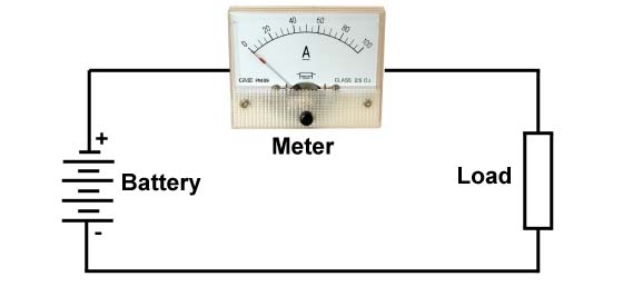
Shown above is a typical ammeter circuit. The current flowing from the power source to the load passes through the amp meter, and the meter displays the amount of current flowing. The meter has a small amount of resistance, thus, there is a small voltage drop across the meter, hopefully a neglible amount.
In my example, I want to use a multimeter that I already own to measure a higher current than it was designed to measure. The Radio Shack Digital Multimeter that I already own has a 10 amp range, which is not enough to measure the battery current on my bike. It also has a 100 MV range. I want to make a shunt to place across the 100 MV range of the meter which will allow me to measure currents up to 100 amps. The resistance of this shunt must be such that when 100 amps passes through the shunt, there will be a voltage drop of 100 MV, which is the full scale range of the meter, and will also be easy to read on the digital readout, since 1 mv will indicate a 1 amp current flow.
To calculate the proper resistance for the shunt, we simply need to use Ohm's Law, which states that the Resistance of a circuit is equal to the voltage divided by the current. Thus, the necessary resistance of our shunt resistor should be 0.1V / 100A = 0.001 ohms.
Now we need a material out of which to make the shunt. We know from the previous discussion that even copper wire has some resistance, and since we need only 1/100th of an ohm, we should be able to find copper wire that will serve as our shunt. It turns out that 12 gage solid copper wire is suitable, and readily available at any hardware store. It has a resistance of 1.588 ohms per 1000 feet, or 0.0001323 ohms/inch. Our 100 MV meter will therefore need to measure the voltage drop across 7.56 inches of 12 gage solid wire.
To make sure that the resistance of the contacts at the ends
of the wire do not influence the reading, we need to place sense wires
on our shunt. So we start with a longer piece of wire, and solder sense
wires to two points exactly 7.56 inches apart. 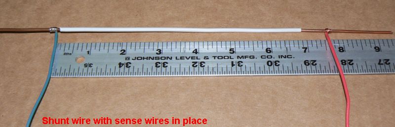
The above photo shows the sense wires soldered in place on our shunt. The sense wires can be any length and size, since they are carrying only minute amounts of current. These sense wires will be attached to the meter, while the ends of the 12 gage shunt wire will be attached in series with the circuit to be measured.
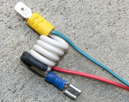
This photo shows the completed shunt after trimming some of the excess wire off the ends and winding it into a small coil to reduce it's bulk. I put blade connectors on the ends of the shunt to make it easy to insert the shunt into the battery circuit of my bike. This shunt was made from common house wiring which can be purchased at Home Depot, but more likely, if you are an average homeowner, you will have a short piece of it available in your basement.
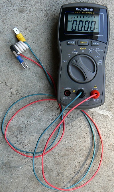
This is my complete metering setup, ready to be used to measure the battery current on my X-Treme XB-500 bike. All I have to do is open the top of my battery case, and connect the shunt into the circuit between two batteries. The meter will read 0 to 100 amps with a resolution of 0.1 amps. This method of building a shunt should be accurate to about plus or minus 3 percent, which is sufficient for the kind of measurements we will be making on our bikes.